Spoke tension and wheel truing: what the sources actually say
Read in the original document: ISO 4210-7:2023 in full —ten pages, not one value in millimetres—, tables 6.1 and 6.2 of two DT Swiss technical manuals, Ford's thesis (2018) and Gavin's paper (1996) end to end, and three Park Tool guides. Not read: ISO 4210-2:2023, which is where the runout threshold lives and which costs money — it is cited through part 7 and said so. The tension ratio between the two sides of a rear wheel is published by nobody: here it is derived from statics, with the code that validates it.
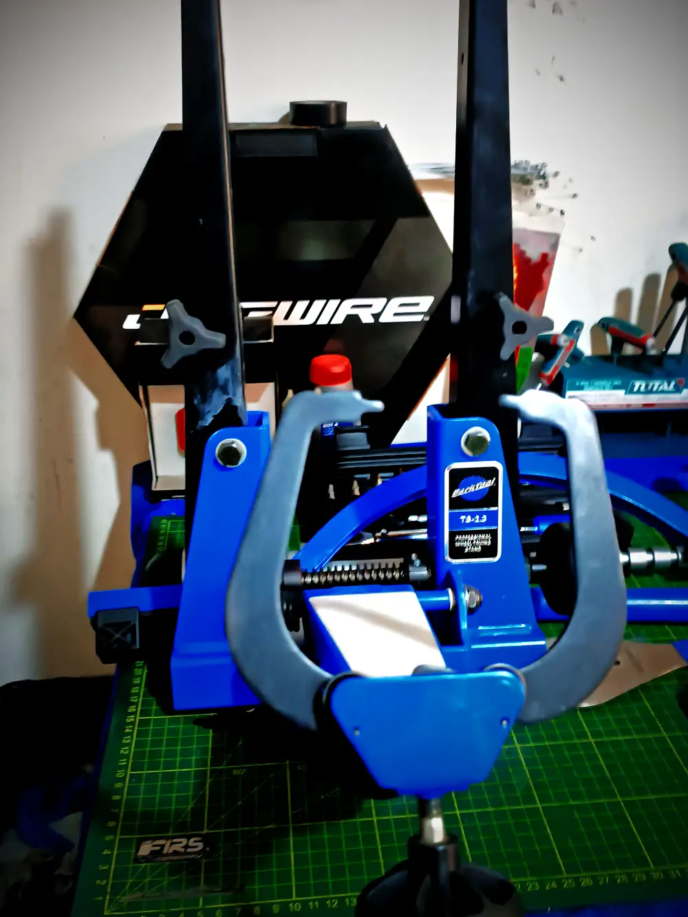
A spoke rings. Flick it with a fingernail and it gives you a note. Build a few wheels and you end up tuning by ear without deciding to, and when one goes flat you hear it before the dial indicator shows it.
That's first-year physics —the frequency of a string depends on how hard you pull it— and it's also the first thing anyone learns standing in front of a truing stand. What almost nobody learns is how much tension ought to be in there. Ask ten shops. You'll get ten answers. And eight of those ten will tell you, with the calm confidence of somebody repeating something they heard properly, that half a millimetre of lateral runout is what the ISO standard demands.
It doesn't. I went and looked.
Before that you need to know what holds up what, because most people have it backwards and it isn't their fault: the wheel lies to you.
A spoke is a wire. It pulls. It never pushes: compress it and it buckles and does nothing at all. So when you see thirty-two spokes holding up somebody who weighs eighty kilos, what you are looking at is not the top ones hanging the bike. It's a rim that arrived from the factory squeezed by thirty-two wires all pulling toward the hub at once. The rim lives in compression. It's a ring with too much diameter and nowhere to stretch.
You get on and the wheel flattens slightly where it touches the ground. The spokes down there lose tension. The ones up top gain almost nothing. Your weight doesn't come down through the upper spokes: it transfers because the bottom ones stop pulling.
Everything else follows from that. If resting tension is enough, the bottom spokes slacken a little each revolution and come back, and the cycle they see is small. If it isn't enough they reach zero, hang loose for an instant and snap back into load. A spoke doesn't break from pulling hard. It breaks from letting go and pulling again, turn after turn, for years.
Anyone who has rebuilt a loose wheel knows that with their hands. What follows is what happens when you ask the sources for the number.
MODULE_01 // THE TABLE
DT Swiss publishes it. And publishes it properly: in newtons, split by brake type and by use, in table 6.1 of its technical manuals —the Spline series one, document WXD10000000861S, version 2024.06, and the Dicut one, WXD10000000860S, same date—. The header carries a precision worth thanking them for: the values are for the tightest side of the wheel, not the wheel as a whole.
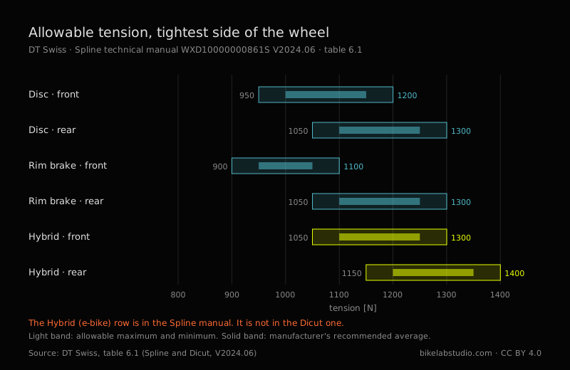
| Wheel | Maximum | Minimum | Recommended average |
|---|---|---|---|
| Disc · front | 1200 N | 950 N | 1150 – 1000 N |
| Disc · rear | 1300 N | 1050 N | 1250 – 1100 N |
| Rim brake · front | 1100 N | 900 N | 1050 – 950 N |
| Rim brake · rear | 1300 N | 1050 N | 1250 – 1100 N |
| Hybrid (e-bike) · front | 1300 N | 1050 N | 1250 – 1100 N |
| Hybrid (e-bike) · rear | 1400 N | 1150 N | 1350 – 1200 N |
That last column isn't a value, it's an interval, and that's how the original has it: DT Swiss doesn't recommend a number but a band inside the window. I've left it as it stands, because tidying it up would mean inventing a precision the manufacturer doesn't give.
The bottom row is the only manufacturer figure I've managed to find that puts a number on what an e-bike motor asks of a wheel. A hundred newtons more ceiling than the equivalent disc rear. It's in the Spline manual and it isn't in the Dicut one, which is the road range and carries no e-bike wheels.
Now, why you've never seen it. In the PDF those numbers don't say 1200. They say 1 200, with a thin typographic space in the middle. Search for «1200» inside that document and you get nothing. Not one hit. To read the table I had to download the PDF and decompress its internal streams byte by byte, because not even the viewer's own search sees them. A manufacturer figure, free, published, verifiable. And structurally invisible to any machine that goes looking for it. It isn't hidden: it's published in a way that stops it circulating, which is not the same thing but comes out fairly close in the end.
MODULE_02 // HALF A MILLIMETRE
ISO 4210-7:2023 is the part of the standard that deals with wheels and rims. Ten pages. Second edition, January 2023, committee ISO/TC 149/SC 1. Its scope, in its own words, is «specifies wheel and rim test methods for ISO 4210-2».
I read it end to end. And here's what nobody tells you: it contains not one single value in millimetres. None. It has forces in newtons, it has durations in minutes, it has two figures with a dial indicator rigged up —one for city and trekking, one for road— explaining how rotational accuracy is measured. How it's measured, not how much is allowed.
And it says where the figure lives. In clause 4.4, setting up a test, it requires lateral runout to be checked in accordance with ISO 4210-2:2023, clause 4.10.1. That's the exact address of the number.
I haven't read that part 2. It costs money. The sample PDF comes encrypted with the permissions locked and you don't break encryption. So the number exists, it has a known address, and almost nobody has gone to that address — me included. That's what there is, and I'd rather say it that way than pretend the standard says nothing.
Because then the half millimetre doesn't come from ISO. It comes from Park Tool, from their truing guide of 31 March 2021, and it comes stated with all the honesty in the world:
«As a general guideline, try for 0.5 millimeters or less of lateral deviation.»
A general guideline. That's what it is. And on the same page they give a millimetre for radial runout —twice the margin— for a workshop reason I wish got repeated as often as the number does: the wheel is going to have a tyre on it, and tyres aren't manufactured to that precision.
In table 6.2 of the two manuals already cited, DT Swiss specifies for its own wheels 0.3 mm of lateral runout in carbon and in welded aluminium, 0.4 in aluminium with a sleeve. The same value for rim brake as for disc, which throws a lot of people who assume disc is more forgiving.
Park Tool 0.5. DT Swiss 0.3. Nearly double, between two authorities nobody disputes. I looked for that comparison in Spanish, English and Portuguese, and in both manufacturers' documentation; I found it nowhere. It may be on some forum I didn't see.
They don't flatly contradict each other, to be clear: Park Tool writes a guide for any wheel that comes into a shop, DT Swiss a product spec for its own. But whoever quotes «0.5» as though it were universal is working looser than the maker of that wheel allows. And whoever quotes it as normative is quoting something they haven't opened.
MODULE_03 // THREE HUNDRED AND SEVENTY
I'll stay inside the standard a moment longer, because there is something it does distinguish that never gets said in the workshop.
ISO 4210 knows four types of bicycle: city and trekking, young adult, mountain and racing. I searched the whole document for «downhill» and «BMX». Zero hits. They don't exist in there.
For each of those four types it sets a force on the rim in the static strength test. Three of them, 250 N. Mountain, 370. Forty-eight per cent more.
And look at two details of the method, which are worth more than the number. First: the force goes perpendicular to the plane of the wheel. It isn't the rider's weight, which would be radial. It's a sideways shove. Second: the test measures permanent deformation — the rim position is noted, load is applied for a minute, released, left to settle another minute, and measured again. What gets checked is not how far it bends, but whether it stays bent.
There's a third, and it's the one that made me raise an eyebrow. On a rear wheel, the force is applied from the cassette side. That is, pushing toward the non-drive side, which is the one carrying less tension. Whoever wrote that standard knew exactly where a wheel gives.
So the standard does distinguish disciplines. Not by tolerances: by the lateral load it demands you survive. And downhill, which is where the most lateral load there is, sits outside the document. That gap is covered by another paper: DT Swiss classifies use in five ASTM categories, from paved road to downhill and freeride, and publishes a maximum system weight per wheel model. Two documents that complete each other and that nobody reads together.
MODULE_04 // FORD
Among riders it goes around that more tension makes the wheel stiffer. It makes intuitive sense: tightening sounds like hardening, and on top of that a tight spoke rings higher when you flick it, same as a string.
Among wheelbuilders the opposite goes around: that tension doesn't affect stiffness as long as no spoke goes fully slack under load.
Ford measured, simulated and calculated, and wrote this on page four of his thesis:
«Contrary to both popular belief and expert consensus, increasing spoke tension reduces the lateral stiffness of the wheel, which I demonstrate through theoretical calculations, finite-element simulations, and experiments.»
Raising tension reduces lateral stiffness. And in section 2.6.2 he lists the two beliefs, the rider's and the professional's, and finishes them off together: «Both of these views are incorrect.»
The mechanism is worth more than the headline, and it's written in a single equation. The stiffness of each lateral deformation mode of the wheel is this:
The first two terms add: the first is what the spokes contribute, the second what the rim contributes through its bending and torsional stiffness. The third one subtracts, and what sits inside it is the tension.
In plain terms: tension comes in through two doors that push opposite ways. Through one, a tight spoke resists being moved sideways more —the guitar-string effect, the one everybody intuits—. Through the other, those thirty-two spokes pulling toward the centre are compressing the rim, and a compressed rim is a ring that wants to buckle. Think of a plastic ruler you press from both ends: it holds, it holds, and then it jumps to one side. The rim is in that situation the whole time.
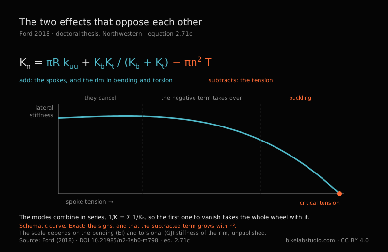
At low tension the two effects cancel almost exactly, and that's why measuring in that range gives you nothing: the wheel looks indifferent. At high enough tension the negative term starts to run the show and lateral stiffness drops. Keep going up and you reach a critical tension where lateral stiffness vanishes and the wheel buckles: it leaves its plane and doesn't come back.
What I liked most about all this is who it rescues. Damon Rinard had measured years earlier that a wheel's stiffness didn't change appreciably with tension, and that result seemed to leave Ford exposed. It doesn't: figure 2.7 of the thesis includes Rinard's data, reproduced with permission, and it fits without forcing anything. Rinard measured in the range where the two effects cancel. He was right where he measured. Ford explains why that range exists and what happens when you leave it.
And careful with what this doesn't say, because I can see the easy reading coming. It doesn't say build them slack. High tension is still the only thing keeping a spoke from reaching zero under load, which is what actually breaks them. What it says is that tension is not a stiffness lever, and that whoever gives it another quarter turn «so it feels firmer» is paying something and buying nothing.
MODULE_05 // SEVENTY-SIX SPOKES
Gavin instrumented three rear wheels of different lacing with strain gauges —Micro-Measurements EA-13-23005-120, Wheatstone bridge with a thermal compensation arm, accuracy of ±2 microstrain— and went out riding on them. Then he took spokes into the lab and broke them in fatigue. Seventy-six of them.
«In 68 spokes the failure occurred at the cold-worked elbow; in the remaining 8 spokes the failure occurred at the threads.»
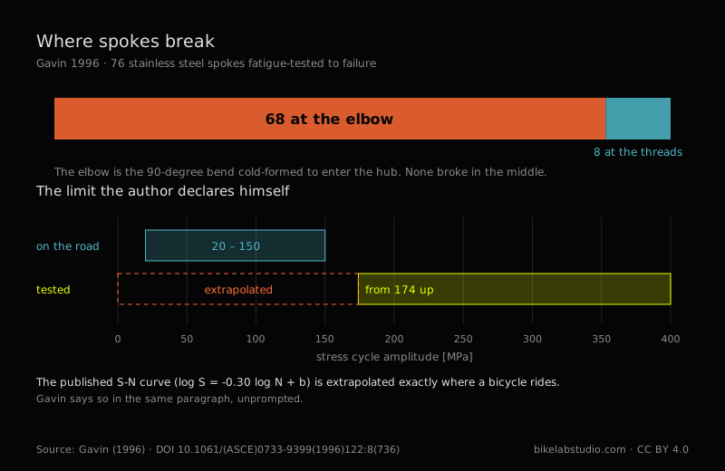
Sixty-eight at the elbow. The elbow is that ninety-degree bend the spoke makes to enter the hub, cold-formed during manufacture, with hardened metal and residual stresses it was born with. Gavin calls it, in those words, «this fatigue critical detail». The remaining eight broke at the threads, where the roots of the thread concentrate stress. None through the middle.
If a spoke breaks on you, the first thing is to look at where it parted. It's telling you what happened.
And here something I let slide earlier comes due. I said «a spoke is a wire» and left it at that, and a good spoke is not a wire of constant section: it's thinner in the middle than at the ends. A 2.0/1.8/2.0 has two millimetres at the tips and 1.8 along the long stretch. That looks like weakening it and does exactly the opposite. The thin zone stretches more for the same load, and by stretching more it absorbs part of the cycle that would otherwise arrive whole at the ends. The middle is thinned precisely to unload the elbow and the thread, which is where the seventy-six break.
Gavin also published his fatigue curve —log S = −0.30 · log N + b, with b̄ = 4.12 and a coefficient of variation of 0.017— and measured that on the road the extreme cycles run around 150 MPa, and that each cycle at that level consumes a millionth of the spoke's fatigue life. At 472 cycles per kilometre that works out to very long lives, provided tension is correct and even.
Everybody quotes those parameters. Almost nobody quotes the paragraph next door:
«The smallest stress cycle in the fatigue tests was 174 MPa, whereas the stress range from the road test data was 20 MPa to 150 MPa. Hence, the fatigue data was extrapolated to the low stress range.»
He tested from 174 MPa upward. The bicycle rides between 20 and 150. The curve is extrapolated exactly across the stretch where it gets used, and he says so himself, unprompted, explaining why: testing a single sample at 40 MPa would have taken an eternity. It invalidates nothing. It places the figure. Repeating his numbers while keeping quiet about that turns an author's honesty into a precision his work doesn't have.
MODULE_06 // IT'S WON IN THE CORNERS
There's a third result of Gavin's that always gets told half way, and I think it has done more harm than good.
Under radial load —weight, nothing else— spoke strain is insensitive to the lacing pattern. Two, three or four cross come out practically the same. From there came the idea that lacing doesn't matter and that arguing about crosses is for nostalgics.
That isn't what the paper says. It says the pattern has its greatest effect under large lateral loads, in a hard corner for instance, and that there long-spoked wheels deform less than short-spoked ones. And it closes in the conclusions that large lateral loads can shorten fatigue life «considerably».
Which means the crosses argument isn't won with weight on top. It's won in the corners.
And look where that leaves us. Ford says what tension reduces is lateral stiffness. Gavin says the pattern matters above all under lateral load. And the only number in the ISO standard that changes with discipline —the 370 N for mountain— is lateral, applied perpendicular to the plane and, on the rear, from the cassette side. Three sources, three methods, forty years between the first and the last, and all three point the same way. Meanwhile the workshop conversation is almost entirely about weight, which is radial, and about how many kilos the wheel takes. We're watching the wrong axis.
MODULE_07 // THE LOOSE SIDE
Every rear wheel with a cassette has a loose side. The drive-side flange sits closer to the centre to make room for the sprockets, so its spokes leave at a shallower angle, and for the rim to end up centred they have to pull harder. The other side ends up below. Always.
The workshop question is how far below, and that figure is published by nobody. I looked in hub makers, in rim makers and in the literature. It isn't there.
But it turns out nobody needs to publish it, because it falls out of statics. The rim can only be centred if the lateral components from the two sides cancel:
And from there, rearranging:
Since the spoke is straight, the sine of the angle is the axial distance from flange to spoke bed divided by spoke length — and that is exact, not an approximation. Which turns the formula into something you can measure with a caliper and without stripping anything:
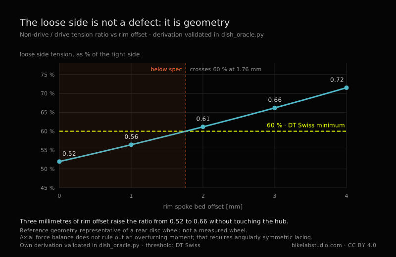
With the geometry of an ordinary disc rear you get a ratio of 0.52: the left side at 52 % of the right. With somewhat different angles it rises to 0.67, which is exactly the order of magnitude you measure with a tensiometer on real wheels. The derivation reproduces what gets observed.
Three things come out of that and they are useful on Monday morning.
The first. That ratio depends on n, on d and on L. On nothing else. It does not depend on how you build the wheel, nor on spoke gauge, nor on how hard you tighten. So «the left side is loose» is not a defect you fix by tightening it. Tighten it and you pull the wheel off centre. Park Tool already said it in prose —«the opposing side will simply have lower tension when the centering, or dish, is correct»—; what was missing was the number.
The second. If with the DT Swiss ceiling of 1200 N the right side runs at maximum, the left sits between 600 and 900 N depending on the hub. That's the real range half the spokes in your rear wheel work in, and it's half of what the table says.
And the third, which is the one I liked best. An offset rim —drilled off centre— moves dD and dN without touching the hub. Three millimetres of offset raise the ratio from 0.52 to 0.66. And with that something appears I hadn't seen written down: DT Swiss asks that the loose side not drop below 60 % of the tight one, and that same wheel with a symmetric rim sits at 52 %. It doesn't get there. It crosses 60 % at 1.76 mm of offset. The offset rim is not a manufacturer's refinement: it's what makes their own rule reachable.
The full derivation, with its limit cases, its analytical derivatives against finite differences and its numerical validation, is published as code in the BikeLab repository. It isn't an experimental result: it's geometry, and anyone can redo it or break it.
MODULE_08 // SIXTY PER CENT
There's a firm conviction in the trade: more weight, more spokes. Thirty-two for normal use, thirty-six if you're heavy, twenty-four if you're chasing light.
I went looking for the test. ScienceDirect, Springer, MDPI, Taylor & Francis, IOP, ASME, SAE. It isn't there. The brands don't publish weight limits by spoke count either.
The explanation turned up in another DT Swiss manual, the ASTM and system weight one, and I find it more interesting than the table that doesn't exist. The manufacturer doesn't bound the wheel by spoke count. It bounds it by maximum system weight, model by model, and by use category. And it publishes a split rule I haven't seen quoted anywhere:
«Max. system weight [kg] (rider+bike+equipment+luggage). The maximum permissible static wheel load is 60% of the maximum system weight.»
Rider plus bike plus luggage, and from there comes static load per wheel with the split declared. An XR 1700 Spline allows 110 kg of system. An FR 1500 Classic, 140. An HU 1900 Spline, which is cargo and motor, 180.
That the weight-to-spokes table doesn't exist isn't a hole in the literature. It's that the industry solved the problem on another axis, and spoke count stayed inside, as a design variable, never reaching the sheet the user reads.
MODULE_09 // WHAT ISN'T THERE
An article that only reports what it found is reporting half.
Tensiometer accuracy. Neither Park Tool nor DT Swiss publishes the error of its instruments. Park Tool describes the TM-1 precisely —it flexes the spoke between two supports with a calibrated spring and what you read is that deflection, which you then convert with a table depending on material and gauge— but there is no ±% anywhere. The device the decision is made with doesn't declare its uncertainty. That's the gap that bothers me most of all of them.
Where the ±20 % comes from. Park Tool sets that a wheel with all spokes within ±20 % of the mean has acceptable relative tension. Half the world uses it and it strikes me as reasonable. I didn't find the test it comes from. A percentage without a derivation is a convention, and it doesn't matter how good it is: it has to be called by its name.
Commercial S-N curves. No spoke manufacturer publishes one for its models. Gavin's data is from 1.83 mm spokes of the mid-eighties.
Sapim. Technical documentation behind mandatory registration. I didn't create an account.
Brandt. The Bicycle Wheel has no edition accessible by legitimate means. Everything circulating attributed to that book stays unverified until there's a copy in front of me.
And the one I wanted most is missing. I looked for studies on factory wheel-build quality —what tension and what spread new wheels come out of the box with— and there are none. It figures: the wheel maker isn't going to publish that its own come out badly tensioned, and the tool maker sells the tensiometer, not the data.
Looking at that list together there's something I didn't see while writing it. A typographic space that makes a table unreadable. A paid standard whose sample PDF comes encrypted. A manufacturer hiding its datasheets behind a registration. An out-of-print book with no legitimate edition. Four different mechanisms, unrelated to each other, and one single outcome: information that exists, that is correct, that somebody took the trouble to produce, and that doesn't circulate. None of the four is censorship. All four work as if they were.
It's worth looking at where each of the numbers in this article comes from, because they don't come from the same place or the same decade. Jobst Brandt wrote his book in 1981 from the workbench. Henri Gavin glued gauges to the spokes of three wheels and published in the ASCE in 1996. Matthew Ford defended a 137-page thesis at Northwestern in 2018, with finite elements and a test rig. Park Tool wrote a service guide in 2021. DT Swiss printed a product sheet in 2024. Forty years, five different trades, no coordination between them. When five sources like that agree on something, that something is almost certainly real: arriving at the same place by five roads that don't talk to each other doesn't happen by accident. When they don't agree, the disagreement flags that there's a judgement call there and not a measurement. And a judgement call can be argued with.
A wheel is a rim compressed by wires that only pull, and it holds because none of them wins. Almost everything said about it can be sorted into three piles: what has been measured, what is somebody's good judgement, and what gets repeated because it gets repeated. The first pile is smaller than it looks.
MODULE_10 // THE THREE PILES
Everything that came up here, sorted. Not by topic: by what kind of thing each claim is, which is what decides how much weight it can hold.
| MEASURED — THERE IS A TEST OR A SPECIFICATION BEHIND IT | |
| Allowable tension on the tightest side: 950–1200 N disc front, 1050–1300 rear, 900–1100 rim brake front, 1150–1400 e-bike rear | DT Swiss, table 6.1 |
| Lateral runout 0.3 mm in carbon and welded aluminium, 0.4 in sleeved aluminium. Same for disc as for rim brake | DT Swiss, table 6.2 |
| The standard test applies 370 N to mountain and 250 to the other three, perpendicular to the plane, and on the rear from the cassette side | ISO 4210-7:2023 |
| 68 of 76 spokes break at the cold-worked elbow; 8 at the threads; none through the middle | Gavin, 1996 |
| Fatigue curve log S = −0.30 log N + b, and its working range extrapolated | Gavin, 1996 |
| Raising tension reduces lateral stiffness, and there is a critical tension where the wheel buckles | Ford, 2018, §2.6.2 |
| Lacing pattern is indifferent under radial load and decisive under large lateral load | Gavin, 1996 |
| Static load per wheel is 60 % of maximum system weight | DT Swiss, ASTM manual |
| DERIVED — NOBODY MEASURES IT, BUT IT FOLLOWS FROM STATICS | |
| TN/TD = (nD/nN)(sin αD/sin αN): the ratio between sides is pure geometry, it doesn't depend on how you build or how hard you tighten | Axial equilibrium of the rim |
| On an ordinary disc rear, the non-drive side sits at 52 % of the drive side; between 600 and 900 N when the other runs at 1200 | The above, with real geometry |
| A 3 mm offset rim raises that ratio from 0.52 to 0.66 without touching the hub; the 60 % threshold is crossed at 1.76 mm | The above |
| JUDGEMENT — SOMEBODY WITH A GOOD EYE SET IT, AND THERE IS NO PUBLISHED TEST BEHIND IT | |
| 0.5 mm lateral runout, 1 mm radial, as a workshop guideline | Park Tool, 2021 |
| ±20 % spread about the mean as acceptable relative tension | Park Tool, 2021 |
| 100–120 kgf as a generic rim range — with the tyre unpressurised, a condition almost everyone drops when quoting it | Park Tool, 2021 |
| NO BACKING THAT I COULD FIND | |
| The rider weight → spoke count table | Seven scientific databases and the manufacturers |
| The accuracy of a tensiometer, in ±% | Park Tool and DT Swiss |
| S-N curves for commercial spokes | The manufacturers themselves |
| What tension and what spread factory wheels arrive with | Zero results |
They are good judgements. I use them. But a judgement is not a measurement, and calling it by its name doesn't take value away from it: it gives it its own.
And separately, one that fits no pile: the normative runout threshold exists, has an exact address —ISO 4210-2:2023, clause 4.10.1— and I haven't read it. Neither have, probably, most of the people who quote it.
MODULE_11 // DIRECT ANSWERS
Five questions that arrive at this page on their own. Each answer stands alone and carries its source inside, so it can be quoted without dragging the rest of the study along.
How much tension should a spoke have?
DT Swiss specifies, for the tightest side of the wheel, between 950 and 1200 N on a disc front, between 1050 and 1300 on a rear, and between 1150 and 1400 on the rear of an e-bike. These are values for the tightest side: the other side sits below it by geometry, not by a build fault.
Does the ISO standard set half a millimetre of runout?
No. ISO 4210-7:2023 runs to ten pages, describes how rotational accuracy is measured and contains no value in millimetres at all. It refers the threshold to ISO 4210-2:2023, clause 4.10.1, which is a paid document. The 0.5 mm usually quoted is a Park Tool workshop guideline; DT Swiss specifies 0.3 mm for its own wheels.
Does more tension make the wheel stiffer?
No. Ford demonstrated in 2018, with calculation, finite elements and testing, that raising tension reduces lateral stiffness. Tension adds stiffness through one route and compresses the rim through another, and at high tension the second effect dominates. Tension is there to keep a spoke from reaching zero under load, not to harden the wheel.
Why is the left side of my rear wheel looser?
By geometry, and it isn't fixed by tightening it. The cassette forces the drive-side flange closer to the centre, so its spokes leave at a shallower angle and need more tension to centre the rim. The ratio between sides is (n_D/n_N)·(sin a_D/sin a_N) and depends only on the geometry of hub and rim and on the spoke count. Tightening the loose side pulls the wheel off centre.
Where do spokes break?
At the elbow. Of 76 spokes taken to fatigue failure by Gavin in 1996, 68 broke at the cold-worked elbow and 8 at the threads. None through the central section. Where it broke tells you the cause: the elbow points to low tension or poor seating, the thread to stress concentration or overtightening.
A plain-language version comes out of this study: the same numbers and the same sources, told for whoever is standing at the truing stand and doesn't need the derivation.
READ_HOW_MUCH_TENSION_DOES_A_SPOKE_CARRY_➔Ravello Joo, C. E. (2026). Spoke tension and wheel truing: what the sources actually say. BikeLab Studio, Trujillo, Peru. ORCID 0009-0007-5631-7436. https://www.bikelabstudio.com/articles/tension-radios-centrado-ruedas-en.html
Sources
Every figure was read in its source document. Manufacturer PDFs were downloaded and their internal streams decompressed to extract the text; the papers were read end to end. No figure comes from an abstract, a search-engine snippet or memory. Where I couldn't open a source, I say so. Nothing is reproduced from the ISO text beyond its scope, which ISO publishes freely in its catalogue; clauses are cited by number.